I really wanted to write this up as a paper, perhaps for SigGraph. But I’ve never submitted a paper before, and I don’t know how worthy this would be of a SigGraph paper to begin with. So instead, I thought I’d write this up as a blog post–and we’ll see where this goes.
Introduction
This came from an observation that I remember making when I first learned about the perspective transformation matrix in computer graphics. See, the problem basically is this: the way the perspective transformation matrix works is to convert from model space to screen space, where the visible region of screen space goes from (-1,1) in X, Y and Z coordinates.
In order to map from model space to screen space, typically the following transformation matrix is used:

(Where fovy is the cotangent of the field of view angle over 2, aspect is the aspect ration between the vertical and horizontal of the viewscreen, n is the distance to the near clipping plane, and f is the distance to the far clipping plane.)
As objects in the right handed coordinate space move farther away from the eye, the value of z increases to -∞, and after being transformed by this matrix, as our object approaches f, zs approaches 1.0.
Now one interesting aspect of the transformation is that the user must be careful to select the near and far clipping planes: the greater the ratio between far and near, the less effective the depth buffer will be.
If we examine how z is transformed into zs screen space:

And if we were to plot values of negative z to see how they land in zs space, for values of n = 1 and f = 5 we get:
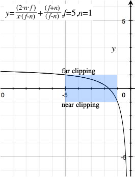
That is, as a point moves closer to the far clipping plane, zs moves closer to 1, the screen space far clipping plane.
Notice the relationship as we move closer to the far clipping plane, the screen space depth acts as 1/z. This is significant when characterizing the accuracy of the representation of an object’s distance and the accuracy of the zs representation of that distance for drawing purposes.
If we wanted to eliminate the far clipping plane, we could, of course, derive the terms of the above matrix as f approaches ∞. In that case:

And we have the perspective matrix:

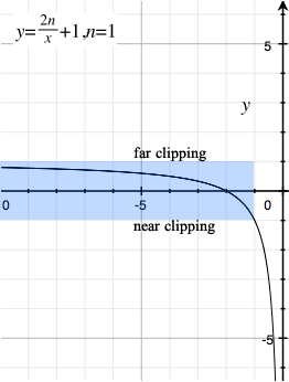
And the transformation from z to zs looks like:
IEEE-754
There are two ways we can represent a fractional numeric value. We can represent it as a fixed point value, or we can use a floating point value. I’m not interested here with a fixed point representation, only with a floating point representation of numbers in the system. Of course not all implementations of OpenGL support floating point mathematics for representing values in the system.
An IEEE 754 floating point representation of a number is done by representing the fractional significand of a number, along with an exponent.
Thus, the number 0.125 may be represented with the fraction 0 and the exponent -3:
What is important to remember is that the IEEE-754 representation of a floating point number is not accurate, but contains an error factor, since the fractional component contains a fixed number of bits. (23 bits for a 32-bit single-precision value, and 52 bits for a 64-bit double-precision value.)
For values approaching 1, the error in a floating point value is determined by the number of bits in the fraction. For a single-precision floating point value, the difference from 1 and the next adjacent floating point value is 1.1920929E-7, which means that as numbers approach 1, the error is of order 1.1920929E-7.
We can characterize the error in model space given the far clipping plane by reworking the formula to find the model space z based on zs:
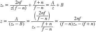
We can then plot the error by the far clipping plane. If we assume n = 1 and zs = 1, then the error in model space zε for objects that are at the far clipping plane can be represented by:
Graphing for a single precision value, we get:
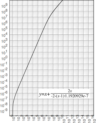
Obviously we are restricted on the size of the far clipping plane, since as we approach 109, the error in model space grows to the same size as the model itself for objects at the far clipping plane.
Clearly, of course, setting the far clipping plane to ∞ means almost no accuracy at all as objects move farther and farther out.
The reason for the error, of course, has to do with the representation of the number 1 in IEEE-754 mathematics. Effectively the exponent value for the IEEE-754 representation is fixed to 2-1 = 0.5, meaning as values approach 1, the fractional component approaches 2: the number is effectively a fixed-point representation with 24 bits of accuracy (for a single-precision value) from 0.5 to 1.0.
(At the near clipping plane the same can be said for values approaching -1.)
All values in the representation range of IEEE-754 points have the same feature: as we approach the value, the representation is similar to if we had picked a fixed-point representation with 24 (or 53) bits. The only value in the IEEE-754 range which actually exhibits declining representational error as we approach that value is zero.
In other words, for values 1-ε, accuracy is fixed to the number of bits in the fractional component. However, for values of ε approaching 0, the exponent can decrease, allowing the full range of bits in the fractional component to maintain the accuracy of values as we approach zero.
With this observation we could in theory construct a transformation matrix which can set the far clipping plane to ∞. We can characterize the error for a hypothetical algorithm that approaches 1 (1-1/z) and one that approaches 0 (1/z):
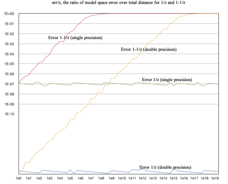
Overall, the error in model space of 1-1/z approaches the same size as the actual distance itself in model space as the distance grows larger: err/z approaches 1 as z grows larger. And the error grows quickly: the error is as large as the position in model space for single precision values as the distance approaches 107, and the error approaches 1 for double precision values as z approaches 1015.
For 1/z, however, the ratio of the error to the overall distance remains relatively constant at around 10-7 for single precision values, and around 10-16 for double-precision values. This suggests we could do away without a far clipping plane; we simply need to modify the transformation matrix to approach zero instead of 1 as an object goes to ∞.
Source code:
The source code for the above graph is:
public class Error
{
    public static void main(String[] args)
    {
        double z = 1;
        int i;

        for (i = 0; i < 60; ++i) {
            z = Math.pow(10, i/3.0d);

            for (;;) {
                double zs = 1/z;
                double zse = Double.longBitsToDouble(Double.doubleToLongBits(zs) - 1);
                double zn = 1/zse;
                double ze = zn - z;

                float zf = (float)z;
                float zfs = 1/zf;
                float zfse = Float.intBitsToFloat(Float.floatToIntBits(zfs) - 1);
                float zfn = 1/zfse;
                float zfe = zfn - zf;

                double zs2 = 1 - 1/z;
                double zse2 = Double.longBitsToDouble(Double.doubleToLongBits(zs2) - 1);
                double z2 = 1/(1-zse2);
                double ze2 = z - z2;

                float zf2 = (float)z;
                float zfs2 = 1 - 1/zf2;
                float zfse2 = Float.intBitsToFloat(Float.floatToIntBits(zfs2) - 1);
                float zf2n = 1/(1-zfse2);
                float zfe2 = zf2 - zf2n;

                if ((ze == 0) || (zfe == 0)) {
                    z *= 1.00012;   // some delta to make this fit
                    continue;
                }

                System.out.println((ze/z) + "t" +
                        (zfe/zf) + "t" +
                        (ze2/z) + "t" +
                        (zfe2/zf));
                break;
            }
        }

        for (i = 1; i < 60; ++i) {
            System.out.print(""1e"+(i/3) + "",");
        }
    }
}
We use the expression Double.longBitsToDouble(Double.doubleToLongBits(x)-1) to move to the previous double precision value (and the same with Float for floating point values), repeating (with a minor adjustment) in the event that floating point error prevents us from propery calculating the error ratio at a particular value.
A New Perspective Matrix
We need to formulate an equation for zs that crosses -1 as z crosses n, and approaches 0 as z approaches -∞. We can easily do this by the observation from the graph above: instead of calculating
We can simply omit the 1 constant and change the scale of the 2n/z term:
This has the correct property that we cross -1 at z = -n, and approach 0 as z approaches -∞.
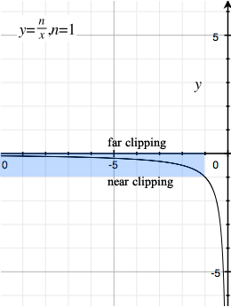
From visual inspection, this suggests the appropriate matrix to use would be:

Testing the new matrix
The real test, of course, would be to create a simple program that uses both matrices, and compares the difference. I have constructed a simple program which renders two very large, very distance spheres, and a small polygon in the foreground. The large background sphere is rendered with a diameter of 4×10¹² units in radius, at a distance of 5×10¹² units from the observer. The smaller sphere is only 1.3×10¹² units in radius, embedded into the larger sphere to show proper z order and clipping. The full sphere (front and back) are drawn.
The foreground polygon, by contrast, is approximately 20 units from the observer.
I have constructed a z-buffer rendering engine which renders depth using 32-bit single-precision IEEE-754 floating point numbers to represent zs. Using the traditional perspective matrix, the depth values become indistinguishable from each other, as their values approach 1. This results in the following image:
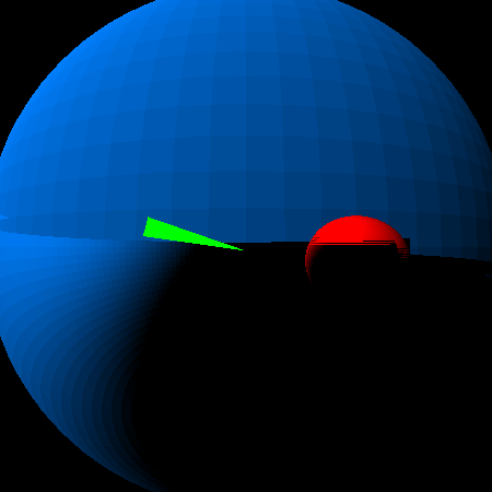
Notice the bottom half of the sphere is incorrectly rendered, as is large chunks of the smaller red sphere.
Using the new perspective matrix, and this error does not occur in the final rendered product:
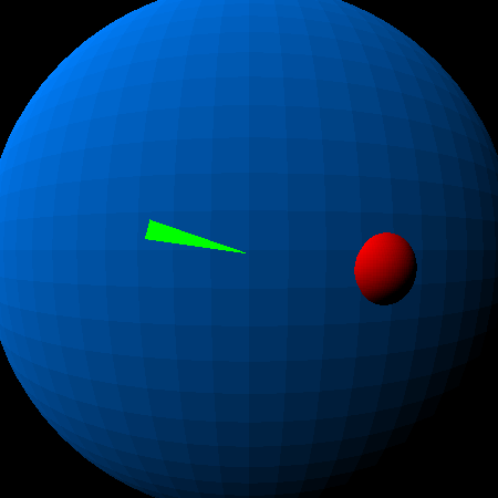
The code to render each is precisely the same; the only difference is the perspective matrix:
public class Main
{
    /**
     * @param args
     */
    public static void main(String[] args)
    {
        Matrix m = Matrix.perspective1(0.8, 1, 1);
        renderTest(m,"image_err.png");

        m = Matrix.perspective2(0.8, 1, 1);
        renderTest(m,"image_ok.png");
    }

    private static void renderTest(Matrix m, String fname)
    {
        ImageBuffer buf = new ImageBuffer(450,450);
        m = m.multiply(Matrix.scale(225,225,1));
        m = m.multiply(Matrix.translate(225, 225, 0));

        Sphere sp = new Sphere(0,0,-5000000000000d,4000000000000d,0x0080FF);
        sp.render(m, buf);

        sp = new Sphere(700000000000d,100000000000d,-1300000000000d,300000000000d,0xFF0000);
        sp.render(m, buf);

        Polygon p = new Polygon();
        p.color = 0xFF00FF00;
        p.poly.add(new Vector(-10,-3,-20));
        p.poly.add(new Vector(-10,-1,-19));
        p.poly.add(new Vector(0,0.5,-22));
        p = p.transform(m);
        p.render(buf);

        try {
            buf.writeJPEGFile(fname);
        }
        catch (IOException e) {
            e.printStackTrace();
        }
    }
}
Notice in the call to main(), we first get the traditional perspective matrix with the far clipping plane set to infinity, then we get the alternate matrix.
With this technique it would be possible to render correctly large landscapes with very distant objects without having to render the scene twice: once for distant objects and once for near objects. To use this with OpenGL would require adjusting the OpenGL pipeline to allow the far clipping plane to be set to 0 instead of 1 in zs space. This could be done with the glClipPlane call.
Conclusion
For modern rendering engines which represent the depth buffer using IEEE-754 (or similar) floating point representations, using a perspective matrix which converges to 1 makes little sense: as values converge to 1, the magnitude of the error is similar to that of a fixed-point representation. However, because of the nature of the IEEE-754 floating point representation, convergence to 0 has much better error characteristics.
Because of this, a new perspective matrix than the one commonly used should have better rendering accuracy, especially if we change the far clipping plane to ∞.
By using this new perspective matrix we have demonstrated a rendering environment using 32-bit single-precision floating point values for a depth buffer which is capable of representing in the same scene two objects whose size differs by 11 orders of magnitude. We have further shown that the error in representation of the zs depth over the distance of an object should remain linear–allowing us to have even greater orders of magnitude difference in the size of objects. (Imagine rendering an ant in the foreground, a tree in the distance, and the moon in the background–all represented in the correct size in the rendering system, rather than using painter’s algorithm to draw the objects in order from back to front.)
Using this matrix in a system such as OpenGL, for rendering environments that support floating point depth buffers, would be a matter of creating your own matrix (rather than using the built in matrix in the GLU library), and setting a far clipping plane to zs = 0 instead of 1.
By doing this, we can effectively say goodbye to the far clipping plane.
Addendum:
I’m not sure but I haven’t seen this anywhere else in the literature before. If anyone thinks this sort of stuff is worthy of SigGraph and wants to give me any pointers on cleaning up and publishing, I’d be greatful.
Thanks.

Hi Bill – realize this was 5 years ago, but did anything ever come of this work? My company builds large geological models at 10^6 – 10^8 distances and your proposed perspective matrix appears to work quite well.
LikeLike
Is anyone monitoring this page any more? I posted a comment almost two weeks ago but it appears to be hung up in moderation.
LikeLike
Apparently the page was being blocked from my local IP address for the past month without my knowing it. Once I got my ISP to unblock the page, I got soooooo. muuuuuuch. notification email…
LikeLike
By the way, I’m glad it worked out.
One interesting trick one can use–I’ve used it myself–is to have objects render which are located at “infinity” by setting w == 0. For example, you can create a star field by converting the ra/deg location of stars in the sky into (x,y,z,0) locations (with the coordinates x,y,z normalized), and they are rendered correctly in the “sky”.
LikeLiked by 1 person
Hi, you ever though about getting rid of the near plane as well? By simply looking at your z-> zs graph I felt the urge to shift it horizontally by “n” so that the function goes from 0 at -inf to -1 at 0
LikeLike
Hate to doublepost but I’m actually trying to kinda do the same thing and this article helped a ton to understand what is wrong with my implementation – I struggled with near clipping and I can see that I use the same matrix that you have here which means I got a near clipping plane at z=1
LikeLike
Hi Bill, a fundamentally amazing tweak to the perspective matrix, and ridiculously easy to implement. After reading through your material, I dropped it into my game engine (OpenGL) with no trouble at all. This should be shouted from the highest tower IMHO!
I have one question if you would – my math isn’t up to it, despite trying. Is it possible to utilise this for orthographic projections as well?
LikeLike
“I have one question if you would – my math isn’t up to it, despite trying. Is it possible to utilise this for orthographic projections as well?”
Well, for orthographic projections you don’t need depth, so you can effectively ignore depth entirely. You can do that by setting the matrix up to force Z to 0 and W to 1.
LikeLike
Great write-up!
This technique was presented by Eric Lengyel at GDC in 2007: http://www.terathon.com/gdc07_lengyel.pdf
and I’ve seen forum posts about this technique as old as 2003: https://www.gamedev.net/forums/topic/139129-typical-near-and-far-plane-values/?tab=comments#comment-1774149
LikeLike